Design Projects

BOTany Design Project

Tasked with the goal of devising our own problem and creating a solution, I was the lead of a team of 4 total engineers to create what we would later call BOTany.

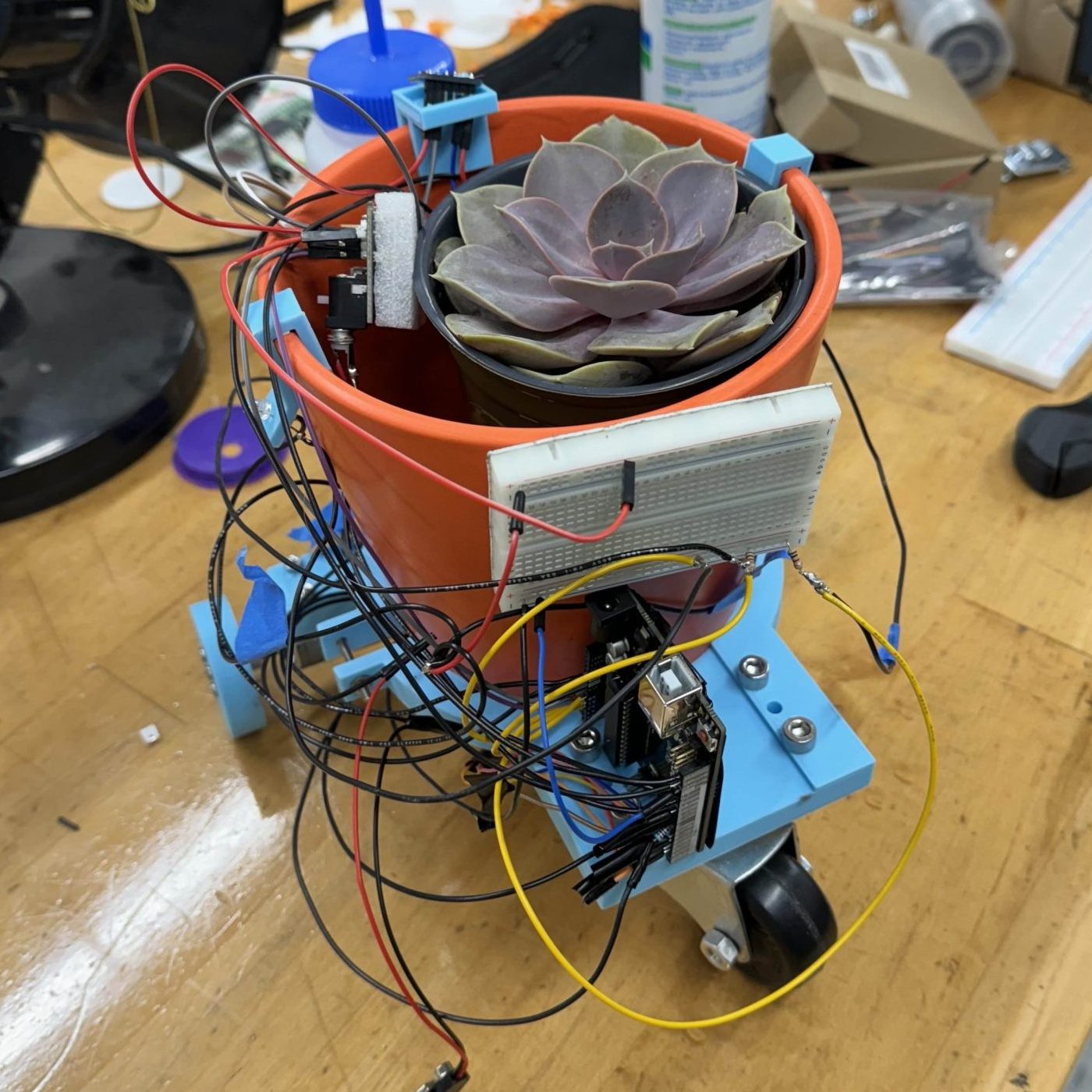
Our goal was to solve the problem of a plant not receiving enough sunlight or even too much sunlight. Our solution was to make a mobile robot that would detect light and move towards and away from light depending on the type of plant.

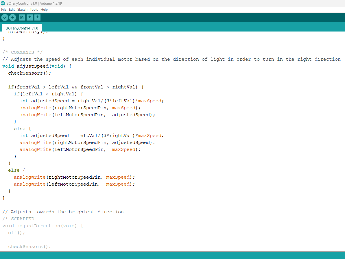
The design seen to the right works through having a front sunlight/UV detecting diode and two cheaper photodiodes to the sides to pinpoint if it’s in sunlight and which direction it should move in.
Teamwork and Planning

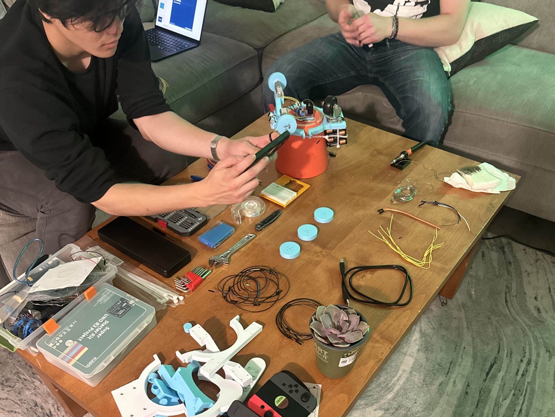
As team leader, it was up to me to organize and plan when our team would meetup and what we would work on individually or as a group. I would work on the software, some would work on research with professors, and others would work on design.

Coding and Deisgning

To test the hardware, I created programs to gather data based off the light sensor and distance sensor on the device to see how we would need to move and where. I also assisted with design work when it came to creating the chassis and creating selecting the motors.

Testing the Product

Testing proved to have some roadbumps but in the end we created a working product that we are proud of. Pictured below is our movement testing.

Self Guided Robot Competition

Divided into groups of 2, our professor tasked us with creating a robot that could travel a course completing an objective. Our grades would be based upon how we perform compared to our peers.

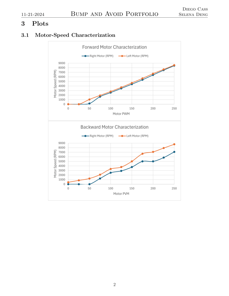
Competition 1 was traveling to and from each end of the course. Competition 2 was grabbing a block and traveling back a different route. These both had specific limitations to our electronics limiting the use of only Legos alongside a maximum number of sensors.

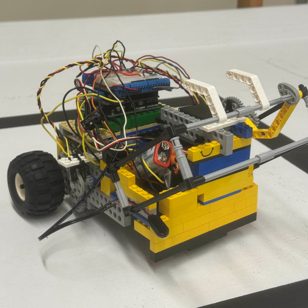
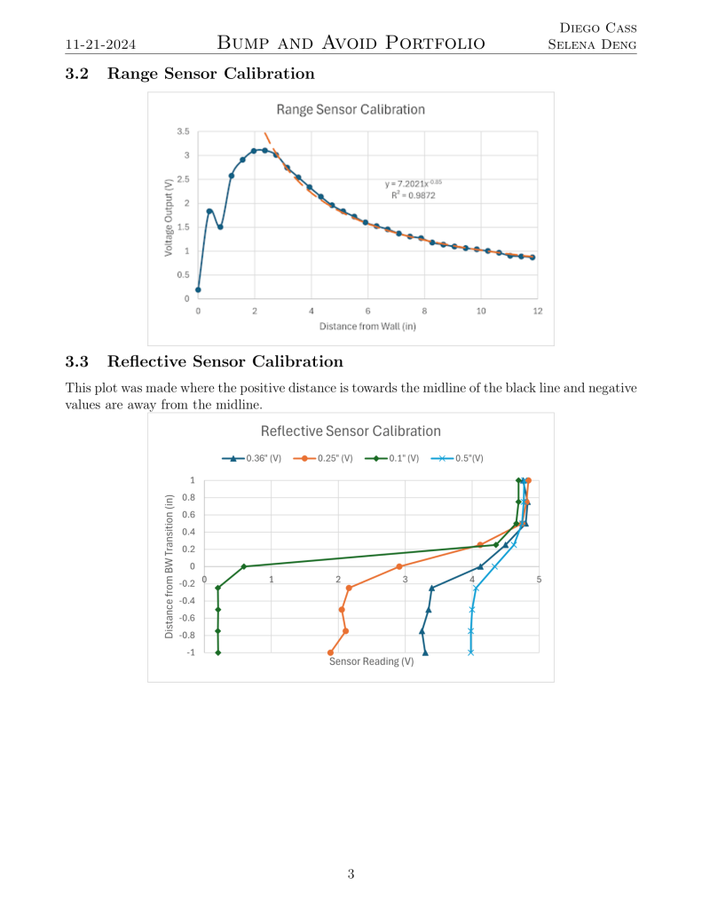
The design seen to the right is implemented during competition 2. This design works through having 2 reflectance sensors on the bottom signalling which side of the line the robot is traveling. The front carriage would drop and drag the objective alongside it.

Mechanisms and Design Selection

The initial competition was to build the frame of the robot and figure out basic movement so the gear ratio was the first. Due to the Lego’s interchangeability, it was incredibly easy to modify the gear train. The initial challenge allowed only limit switches and flex sensors, so we opted for flex sensors due to its ability to detect how much the robot has pushed forward and being able to adjust accordingly. This proved to have some bugs that I tried to code out by allowing a maximum bump amount, but it still had trouble. The next challenge allowed reflectance sensors so we changed our strategy but kept the basic design. Below is our challenge 1 robot attempting the course.

Learning New Controls

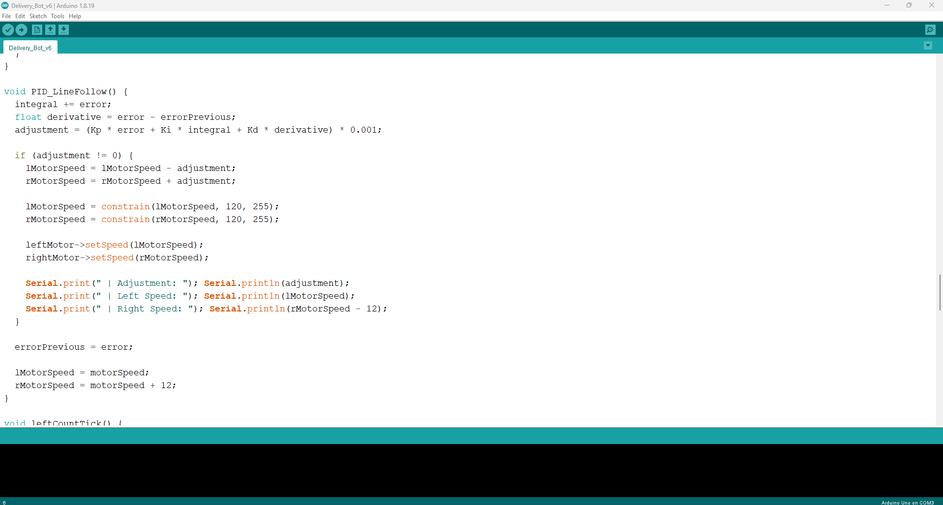
Because the reflectance sensors have an analog value, my partner and I both learned how to create and calibrate a control algorithm to guide the robot. We took time discussing with our teachers assistant to learn about creating a PID controller and came up with the system pictured below, varying the values based on our needs. This system would vary the speed of the left and right motor to make slight adjustments in its direction in order to follow the black line. In the video under Competition Time, you can see the slight adjustments on the long straights especially.

Competition Time

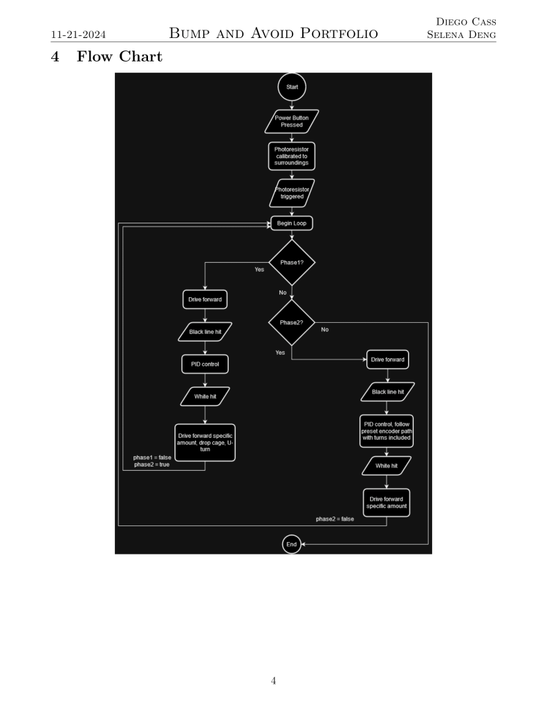
Combining the control algorithm and the physical design, the final part was programming different stages. Using the flow chart below, I created a checkpoint system where, once a certain landmark was hit, it would cycle further into the process. Some checkpoints were somewhat distance based where it would travel a certain distance and, depending on the stage, if it detects white or black, it would cycle to the next step. The distance was created with a break beam sensor attached to a gear next to the motor. These allow the robot to quickly traverse the course without needing any special generalized coding fitting the needs of only the competition. Below is our most successful run.

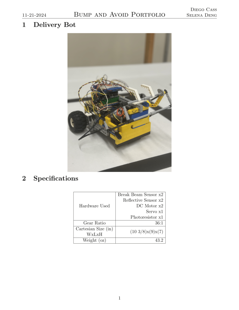
Robot Specifications and Data

RC Car

Throughout a class, my professor guided us towards constructing and rapid prototyping a controlled car to perform tasks on a course.

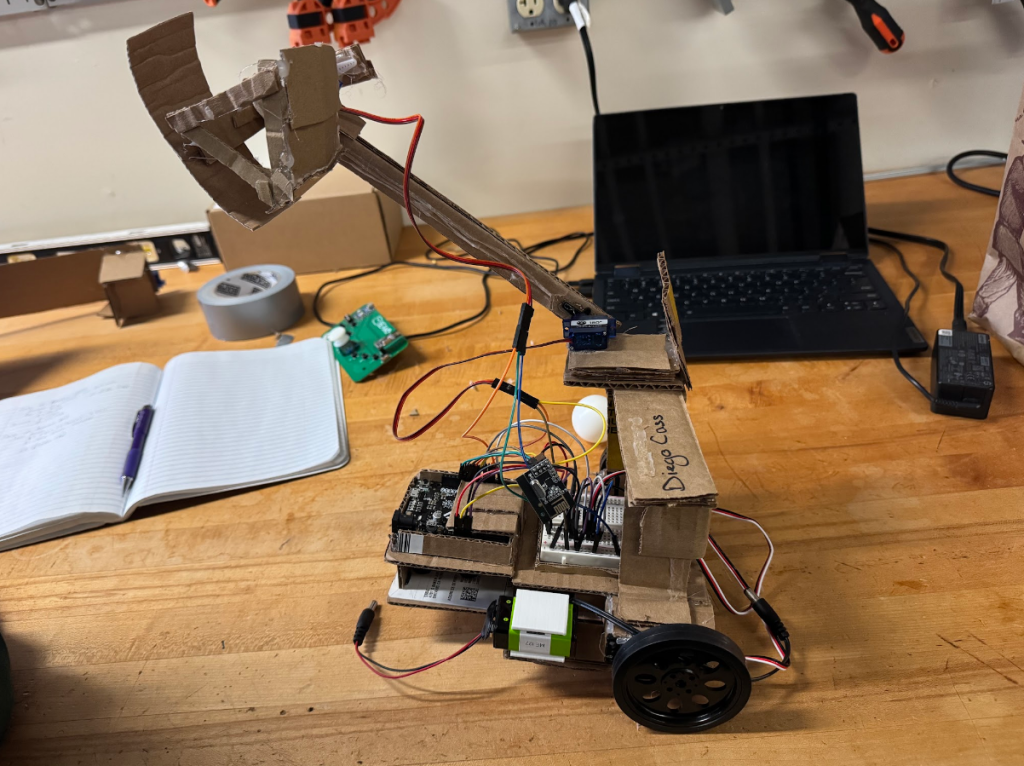
I got an initial package of electronic components to create the car along with a pre-programmed controller and bluetooth receiver. There was a 12x12x12in limit to the design size and cardboard was only allowed with hot glue for constructing the frame.

The design to the right is fitted with a plow arm and tank style steering.

Prototyping Over Time

Scroll to Top